CAN Bus - Connecting to CAN Bus Networks
Author: Christian Kurzke
Recap from Episode 1
With the growing complexity of vehicle functions (more diverse electronic sensors and actuators) the effort to run cables throughout a car became increasingly more cumbersome.
CAN Bus was introduced in the mid 1990’s to solve some of those problems by transitioning from an analog point-to-point wiring scheme to a digital (2-wire) communication bus architecture.
Let’s take a look at how devices can participate in the communication via CAN bus in a vehicle.
Hardware Connectivity
In order for a hardware node to participate in a CAN Bus communication, it needs at a minimum two layers of chipset functionality - which are often combined into (very low cost) SOCs.
Those two layers are:
- A CAN Bus electrical “Level” converter, from the robust +/- 12V differential wire format to a standard 0/5V digital RX/TX protocol.
A typical component for this is the chip MCP2551:

Image source
- A Microcontroller which implements the fundamentals of the CAN Protocol like packet framing, collision detection and priority enforcement etc.
A chip which is frequently used for this is the MCP2515:

Image source
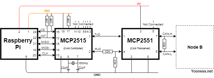
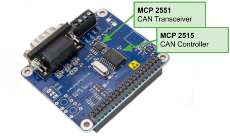
Below is an example of a discrete CAN interface for a Raspberry PI, see details here.

In the following chapters we go in detail through the three lowest layers of the CAN Bus.
For a very detailed description of this topic, see also this eBook or the electrical CAN Bus specifications in ISO 11898-1 and IS0 11898-2 which extends the electrical specifications and signal requirements for driving the bus with data rates up to 1Mbps.
The full specification is available from here.
Electrical Characteristics
In order to communicate on a CAN Bus network, a device has to be electrically connected to the bus, and has to “understand” and “speak” the low-level electrical signals standardized for the particular communication standard.
From a physical point-of-view, the CAN Bus is a two wire differential bus topology. Some of the fundamental principles are:
- Even though there are two wires, there is no dedicated “send” and “receive” wire in CAN. The two wires represent the shared medium between all nodes, and every node can receive and/or transmit at the same time (for now, ignoring collisions of data packets).
- All nodes are typically arranged sequentially in a “bus”, but may with some limitations be arranged as a star or any other graph topology.
- The transmitters are “open collector” or “dominant zero”, where, in the case of multiple nodes transmitting, the node which is transmitting a Zero will win out over the node transmitting a One (This will be significant for the priority resolution of CAN packets)
- The bus is terminated at both ends with a 120 Ohm resistor.
A good illustration of the wiring is shown below.

Here is an example oscilloscope view of what a single CAN package looks like on the bus:

At the electrical connection level, signal converters, to turn the differential voltage levels into digital 1 and 0 bits.
Typically this conversion is done with a very simple Integrated Circuit like a MCP2551 Transceiver. For more info on that, see this example.
Interpreting Ones and Zeros as CAN Packages
Once the signal is processed into bits, the raw bit stream is processed by a CAN Controller according to the low level CAN protocol ISO 11898.
This can for example be accomplished by using a MCP2515 Microcontroller. This controller produces well-formed CAN Packets and handles the physical layer CAN protocol (things like collision control, priority resolution, CRC, bit timing and packet timing, etc.) You can find more info on that here.
For a more flexible architecture, this functionality could also be provided by a Microcontroller such as the Arm based STM32xx family running CAN-USB bridging firmware.
CAN bus low level communication
From the CAN Controller, the payload of the CAN packets is communicated to the CPU. In the example below, the data is passed via a SPI interface to the Raspberry Pi, running a CAN Device driver. Other connection mechanisms are connecting via USB or RS232 serial connections.
At this level, a CAN data packet has the following structure (For more detail see here):

Low Level Protocol Specifications
At the very simplest case, we can think of the CAN Data Packet as having
- 11 bit Packet ID
- 64 bit Payload
- 15 bit CRC Error detection / correction
It is important to understand that the 11 bit packet ID:
- Is neither a sender, nor a destination address. Any node on the bus can technically send CAN packets with any arbitrary ID.
- Indicates the interpretation of the Payload data (e.g. is it the value of engine temperature or wheel speed)
- Arbitrates in case of bus-collisions. The packet with the lowest ID will win, therefore lower IDs are assigned in order of importance
This has interesting security implications, enabling attackers to spoof packets or flood the bus with high priority packets. This article does not go into detail of those issues, a good overview can be found here.
More detailed information on how to communicate with the nodes on the CAN Bus will be presented in the next section.
To find out more about MontaVista's Automotive solutions, you can find more information here. Or contact us if you would like to discuss your new design together!


